Mousetrap Car Plans: Long Distance Traveler
Earth shattering secrets for building record setting and winning mousetrap cars and racers. Here you will find all the latest and greatest untold construction secrets so you can build your very own mousetrap vehicle.
The Basic Kit II is an extreme long-distance-traveler that is a guaranteed winner for any mousetrap vehicle long-distance contest. Major performance upgrades that will give this traveler the advantage over the competition include: adjustable steering and reduced friction bushings. The Basic II Kit is built on our top selling Basic Kit chassis. The Basic Kit II comes ready-to-assemble with pre-cut and pre-drilled parts so you can be ready for action and racing on the same day. As with all our kits, The Basic Kit II comes with step-by-step instructions that are filled with tons of top secret performance tips and tricks that have been developed exclusively by Doc Fizzix so that you will have all the information you need to make The Basic Kit II a winner.

basic kit ii: you will find everything you need inside your basic kit ii mousetrap vehicle kit to build your very own mousetrap racer. the basic kit ii can be ordered from the comforts of your own home through the Doc Fizzix website where it will be shipped directly to your door step.
Making The Frame
The frame is assembled is two sections, a front swivel section and a rear main body section.

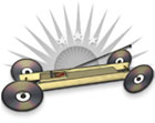
frame: this is the finished example of the frame we are building.

step #1: Start by assembling the front swivel section as pictures. Glue the short deck top between the two short side rails. Be careful to line up all the holes as pictured. Take time to study the image above before you glue anything.

step #2: Using the light weight plastic bolt and nut combination, attach the swivel tongue to the swivel base as pictured. do not glue

step #3: glue the long deck top to the long side rails as pictured.

step #4: glue the rear stabilizer 2-inches from the rear of the vehicle as pictured. The stabilizer is centered in vertically and even with the rear axle holes.

step #5: Use one of the axles placed between the front and rear section to find the correct spacing.

step #6: Working from underneath the frame, glue the swivel support to the main body. Do not glue to the swivel section.
Painting the Frame (optional)
The time to paint the frame is before the wheels and the mouse trap are attached. It is best to lightly sand the frame with 220 or even 360 grit sandpaper.

optional: sanded and painted frame
Assembling the Wheels
Use the following steps to correctly setting up the wheels and axles.

step #1: Press fit the black spacer into your CD or DVD.

step #2: Carefully adjust the CD/DVD on the spacer so that the CD/DVD sits perpendicular to the floor and will also ride true without wobbling.

step #3: It is not always necessary to glue the spacers to the CD/DVD since they are designed to have a tight fit but some people like to use a little white glued to hold the CD/DVD in place. Do not use super glue, super glue can eat into and destroy the material that the CD/DVD is made from.

step #4: place the four micro-ball bearings into each of the pre-drilled axle holes. Never use super glue around bearings, if glue is needed, use some white Elmer's glue on a tooth pick.

bonus tip: soak bearings in WD-40 and then spin them on the tip of a pencil to remove any grease. Repeat several times to insure all the grease is removed.

bonus tip:not required but in this optional tip the bearing casing are removed exposing the bearings themselves. Soak in WD-40 as described above and repeat. Removing the casing helps remove more of the grease and helps reduce friction even more.

step #5: place each of the axles through the front and rear bearings.

step #6: Use a washer between the wheel and the frame to decrease any rubbing friction. Press the wheel set-up onto the axle, do not glue.

step #7: On the other end of the axle place another washer and then place the other wheels set-up with the beveled side of the spacer pointed towards the frame.

step #8: the fit between the axles and bearings should be tight enough that the axle will not move from side-to-side, but if needed, us a tooth pick to applied a small amount of Elmer's glue to the axle in order to prevent the axle from sliding in the bearing.
Attaching the Lever Arm (option #1)
Make sure you understand your contest regulations before you cut the mouse trap. If the contest states that you cannot cut and/or alter the mouse trap then you will need to skip this step and go to Attaching the Lever Arm (option #2). If the contest regulation allow for the mousetrap to be modified to extend the mouse trap's snapper arm then follow the steps listed bellow in order to prepare the mouse trap.
Looking at the mouse trap and take note of where the mouse trap's spring presses on the mouse trap's snapper arm. Using a pair of needle-nose pliers or a wire cutter, cut the snapper arm just before the corner bend on the side of the snapper where the spring is pressing down. Remove and discard the cut section.

step #1: Cut the mouse trap's snapper arm just bellow the corner on the side of the snapper that has the spring pressing down on it as pictured and removed the cut piece.

step #2: Using your needle-nose pliers, pry up on the "U" hook that is pressed into the mouse trap's base in order to remove the locking bar. Discard the "U" hook but save the locking bar for the next step.

step #3: Using your needle-nose pliers straighten the bent end (the non-loop end) of the locking bar.

step #4: Insert the locking bar all the way into one end of the lever arm. Only the locking bar's loop should be all that is sticking out of the lever arm; this will be where the string will be attached. You can glue the locking bar in place or for a better solution a small bend can be placed in the middle of locking bar so that the bar is held in place by it's own pressure, see image.

step #5: Slide the other end of the lever arm over the cut section of the snapper arm. Press the lever all the way down the snapper arm making sure the lever arm goes under the mouse trap's spring as pictured.
Attaching the Lever Arm (option #2)
Some contest rules state that the mouse trap can not be altered from it's original working condition. In this method a lever arm is attached to the side of the mouse trap's snapper arm without cutting the snapper itself so the mouse trap can still be set in the traditional method. This method can be used to secure a longer lever arm to the mouse trap's snapper without having to cut the snapper.

step #1: Attach a lever arm to the side of the mouse trap's snapper using several pieces of picture wire or three small zip-ties as pictured.

step #2: Trim any left over wire/tip-zie and then place a small amount of super glue on the wire/zip-ties to secure them in place and to the snapper arm.
Positioning the Mouse Trap
For maximum performance the mouse trap needs to be positioned on the chassis so that the lever arm falls directly above the drive axle. In order to find the correct placement of the mouse trap on the chassis hold down the lever arm into the fully wound position and then line-up the tip of the lever arm so that it is just reaching the drive axle. Make sure to position the mouse trap so that the lever arm travels along the center of the vehicle and does not hit anything.
If you are building the basic kit "box stock" and have made no modifications to the length of the lever arm then back of the mouse trap should be glued 10 1/4 inches from the drive axle.

step #1: the mouse trap is positioned on the chassis so that the tip of the lever arm lines up with the drive axle when the mouse trap car is fully wound-up.

step #2: to find the correct position for the mouse trap, hold down the lever arm and line-up the mouse trap on the chassis.

step #3: Glue the mouse trap to the frame once the correct position is located.
Attaching the Mouse Trap (optional)
There are many ways to attach the mouse trap to the frame, most will glue the mouse trap and this will work fine but the mouse trap will become permanently attached to the chassis making future adjustments to the mouse trap's location difficult. Doc Fizzix attachments bolts provide a less than permanent way to attach the mouse trap so that the mouse trap can be relocated if needed.

bonus tip: here the mouse trap is attached to the chassis with four Doc Fizzix hold down bolts instead of glue so that the mouse trap can be repositioned if needed.
Doc Fizzix Hold-Down Bolts
Using a 7/64-inch drill bit, drill four holes in the corner of a mouse trap. Mark the position of the mouse trap on the vehicles frame and then using one of the bolts make an indentation on the vehicles frame or using the holes just drilled in the mouse trap as a template and drill the corresponding holes in the frame using the same 7/64-inch drill bit. Attach the mouse trap using the hold down bolts and that is it you are done!

step #1: drill four holes in the corners of the mouse trap.

step #2: Use the holes in the mouse trap as a template to mark where to drill the holes for the mouse trap.

step #3: Attach the Doc Fizzix hold down bolts through the mouse trap and the chassis. If needed, the mouse trap can be repositioned by repeating the steps above.
Attach the Axle Hook
The important part of a winning mousetrap project is Doc Fizzix's "easy-to-wind" and "snag-free " string release system that will not tangle or snag.

step #1: A small zip-tie is positioned in the center of the drive axle and locked in place.

step #2: The zip-tie is trimmed and cut so that the excess tail of the zip-tie. Make sure to trim the excess zip-tie tail as close as possible to the locking hub.

step #3: Super glue the zip-tie to the axle to make sure the zip-tie axle hook does not slip when under tension.

step #4: Catch the zip-tie axle hook with the string loop and wind the string as normal.
How to Make a Loop Knot
It is important for the pulling string to have a correctly tied loop knot in order for the Doc Fizzix "easy-to-wind" and "snag-free " string release system to work properly or the mousetrap vehicle will come to an instant stop. Learning how to tie knots brings me back to my Boy Scout days but is also an extremely important part of building a successful mousetrap car.
Try to carefully study the images on how to tie a loop knot as seen bellow. Please note that the string being used if ONLY for illustrating how to tie the correct knot, it is NOT recommended to use a thick string with mousetrap vehicles. Also, the loop knot should be large enough so that it releases from the drive axle without snagging on the axle hook (see images).

step #1: Fold the string over.

step #2: Tie a traditional knot using the folded part of the string as pictured

step #3: the finished product.
Attaching the String
The string is tied to the tip of the lever arm and then adjusted so that it "just" reaches the drive axle

step #1: Tie the string to the lever tip of the lever arm

step #2: Pull the string towards the drive axle

step #3: tie a loop knot in the string so that the string is "just" long enough to reach the drive axle.
Winding The String
When winding the string around the drive axle make sure NOT to put any slack in the string. The string should be wound tight as it winds around the drive axle or the mousetrap racer may have a jerky motion as the string unwinds. Always wind the string using the full load of the mouse trap, do not help lift the lever arm during the winding process (except maybe at the start of the wind and then only just to get things going.

bonus tip: Never put slack in the string as you wind it around the drive axle. Always wind the string under tension.

bonus tip: some times it is necessary to lift the lever arm in order to start winding the string but then put the string back under tension to make sure the string winds under the force of the mouse trap's spring.
*Can't find what you're looking for? Ask Doc Fizzix »